Moving from the UK to the US creates a few predictable problems for someone who has accumulated old computers and consoles. Plugs are different. Mains voltage is different. Power supplies that sat unnoticed behind a television for years suddenly become objects requiring actual thought.
My old Super Nintendo seemed like one of the easier cases.
It was a European PAL machine—at least, that was what I had always believed. The top of the console literally said PAL VERSION. Back in the UK, I remembered powering it with a PAL Mega Drive power supply. That adapter was no use on American mains, so I bought what appeared to be the correct modern solution: a Rondo Products SNES-Con PAL kit with a Triad 9V DC supply.
I connected it, switched on the SNES, and got absolutely nothing.
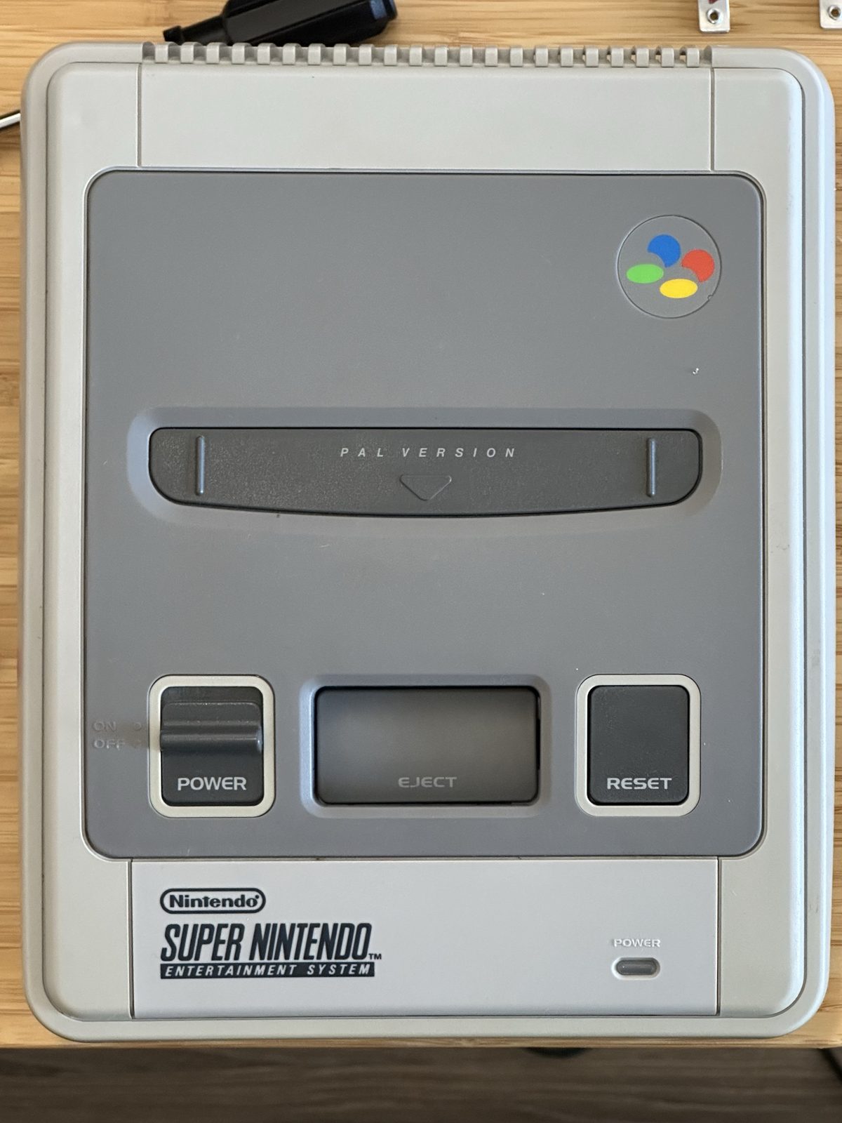
No red power light. No picture. No reassuring signs of life from a console I had owned for years.
At that point, the obvious suspects were the usual ones: perhaps the internal fuse had blown, perhaps the power switch needed cleaning, or perhaps some component had failed while the console was sitting unused. It should have been a simple troubleshooting job.
It was not.
The measurement that made no sense
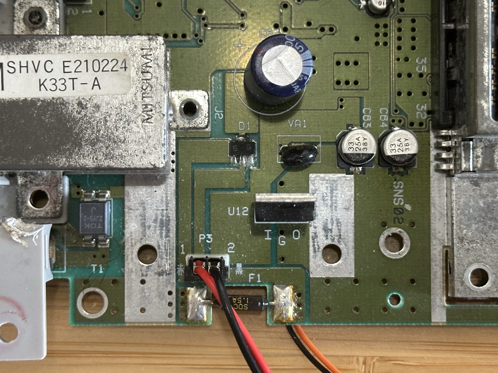
Once the case was open, I started at F1, the internal fuse. It had continuity, so it was not blown. Measuring across the two fuse pads gave 0V—which is exactly what you would expect from a good fuse, because both sides should be at almost the same electrical potential.
The strange result appeared when I measured from either side of the fuse to motherboard ground.
The meter read approximately −9V.
I checked the probe leads at the multimeter. I checked their positions on the SNES. Black was on the heatsink and red was on the fuse. The sign was not a simple mistake: the incoming power rail really was about nine volts below ground.
The power supply was producing roughly the right voltage, but the console appeared to be receiving it backwards.
Following the circuit through the power switch, fuse and KA7805 regulator did not make the situation any less peculiar. There was no useful 5V output from the regulator. Everything was consistent with reverse polarity—but I had bought the adapter specifically intended for a PAL SNES.
And, again, the lid said PAL VERSION.
Looking for a PAL SNES that wasn’t there
The next step was to understand the input circuit. A PAL SNES power arrangement is not identical to the Japanese and North American versions, so I started looking for the components I expected to find on a PAL motherboard.
They were not where I expected them to be.
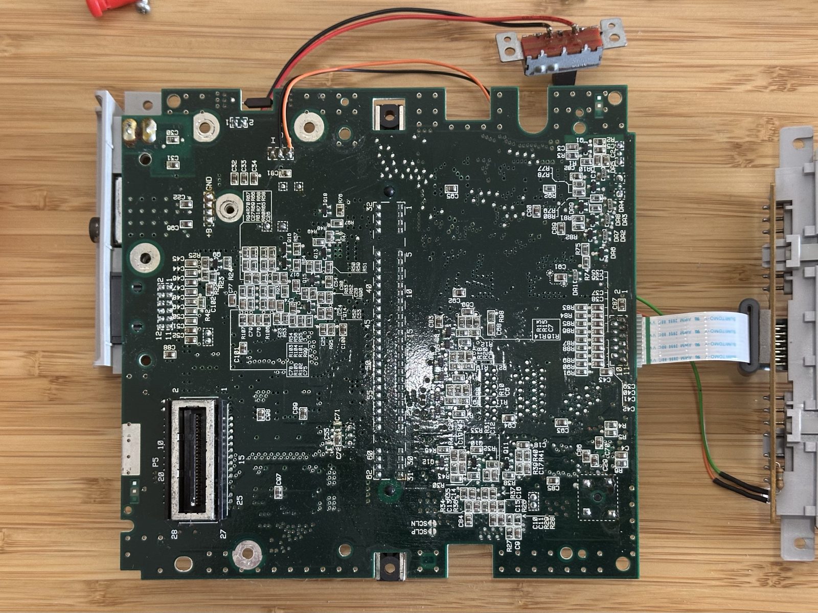
Eventually, the motherboard came completely out of the chassis. Printed prominently on it was the detail that changed the whole investigation:
SNS-CPU-GPM-02
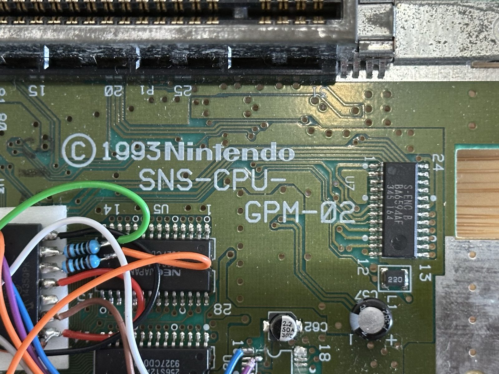
This was not the PAL motherboard I thought I was troubleshooting. The GPM-02 is from the NTSC/Super Famicom side of the SNES family.
Turning the console over produced an even better reveal. The lower label did not identify it as a European SNSP-001A. It said:
SUPER FAMICOM SHVC-001

So the machine in front of me combined a PAL-marked upper shell, a Japanese Super Famicom lower identity, and an SNS-CPU-GPM-02 motherboard.
I don’t know who assembled this combination or when. It looks like someone converted a Super Famicom into a PAL-looking SNES. So a console with an interesting story! Albeit one lost to time. What I can say is what we have: a PAL upper shell, an SHVC-001 lower section, a GPM-02 board, and (as I would shortly discover) some significant modifications.
The old Mega Drive power supply suddenly mattered
Once I knew that the motherboard belonged to the Japanese/NTSC family, my memory of the old power supply stopped being a minor detail.
The PAL Mega Drive Model 1 supply I’d used in the UK produced roughly 10V DC and was centre-negative. That’s a sensible supply for a Japanese Super Famicom-style input. The modern Triad WSU090-1300 I had just tried produced 9V DC at 1.3A through a 5.5×2.1mm barrel connector—but its normal output was centre-positive.
That was a very plausible explanation, but I didn’t want to diagnose the console from model numbers and memories alone. This particular machine had already demonstrated that labels and assumptions can be misleading. The correct thing to do was measure its actual wiring.
With the motherboard unpowered and removed from the chassis, the middle G leg of U12 — the KA7805 regulator — provided an unambiguous ground reference. I traced continuity from that ground point to the DC socket and then to the contacts of a barrel plug.
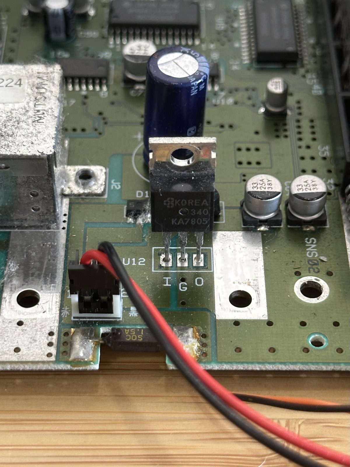
The result was conclusive: the barrel connector’s centre pin was connected to motherboard ground.
This console was centre-negative.
That single continuity test explained the original −9V reading perfectly. The centre-positive supply was not failing to deliver power, and the SNES fuse wasn’t blocking it. Voltage was simply being applied with the opposite polarity from the one this motherboard expected.
Had I damaged it?
Finding the cause was reassuring, but it introduced a less comfortable question: had briefly feeding reverse polarity into a vintage SNES damaged anything?
With all power disconnected, I measured resistance from the 5V output of U12 to ground. The meter briefly showed approximately 80Ω, then climbed rapidly to effectively infinite resistance. That behaviour is consistent with the meter charging capacitance on the 5V rail, rather than finding a persistent short.
It didn’t prove that every component was healthy, but it was encouraging. There was no obvious dead short on the regulated rail.
A second surprise hiding inside
The power-supply mystery was not the only unexpected discovery. The motherboard carried a substantial collection of additional wiring around the CPU and CIC area.
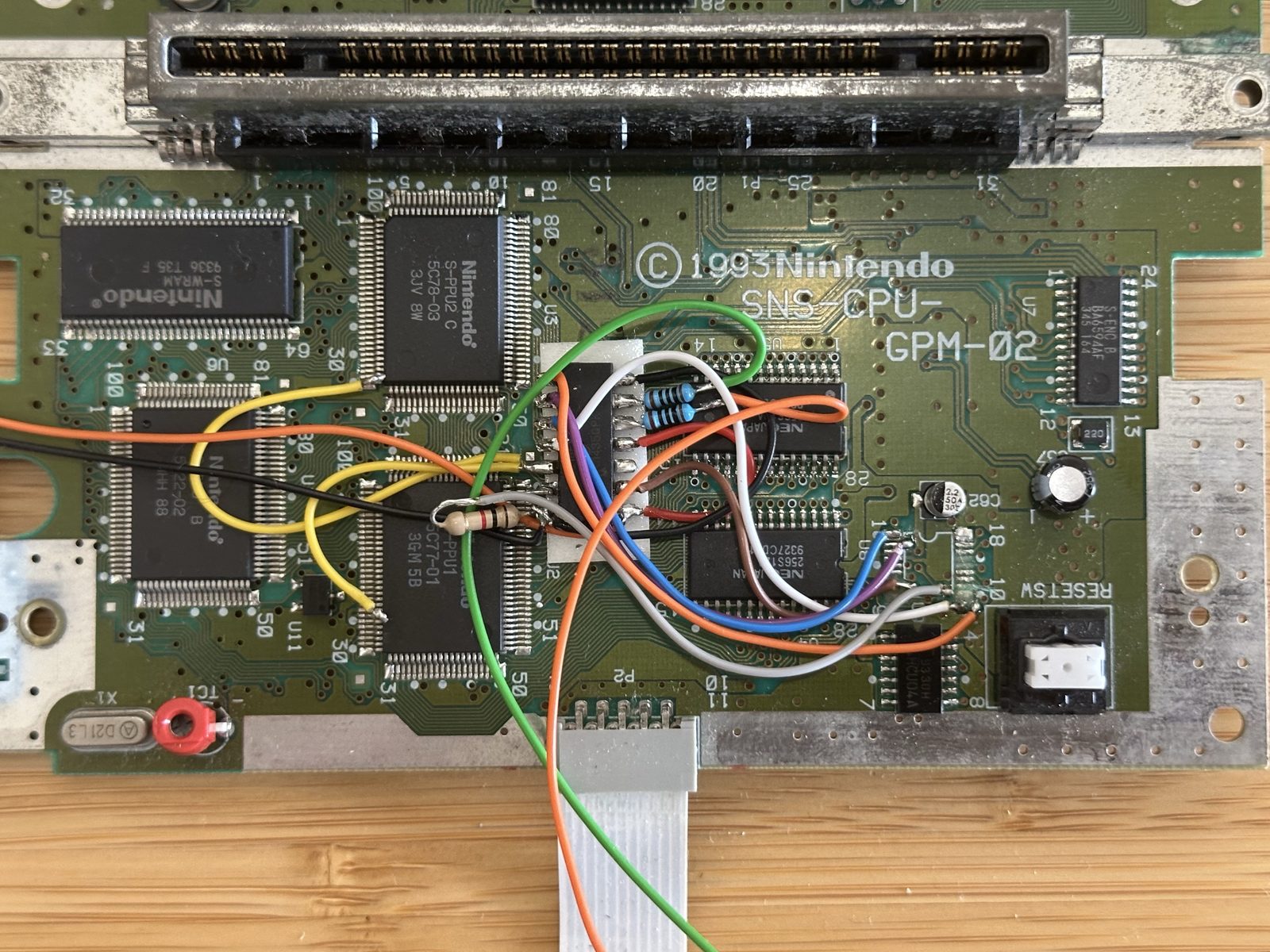
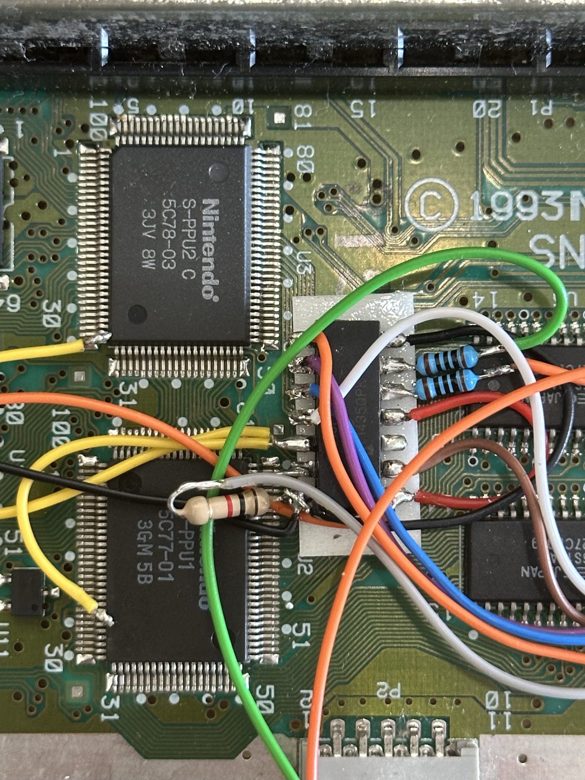
This turned out to be a region-free and selectable 50/60Hz modification. That’s a useful upgrade in its own right, allowing the console to accommodate software from different regions and switch video timing.
The nicest part of the installation was the lack of case cutting. There was no aftermarket toggle switch protruding from the case and no extra hole drilled into the plastic. The modification had been wired into the SNES’s original RESET button.
Put the cover back on and there’s no external clue that anything has changed.
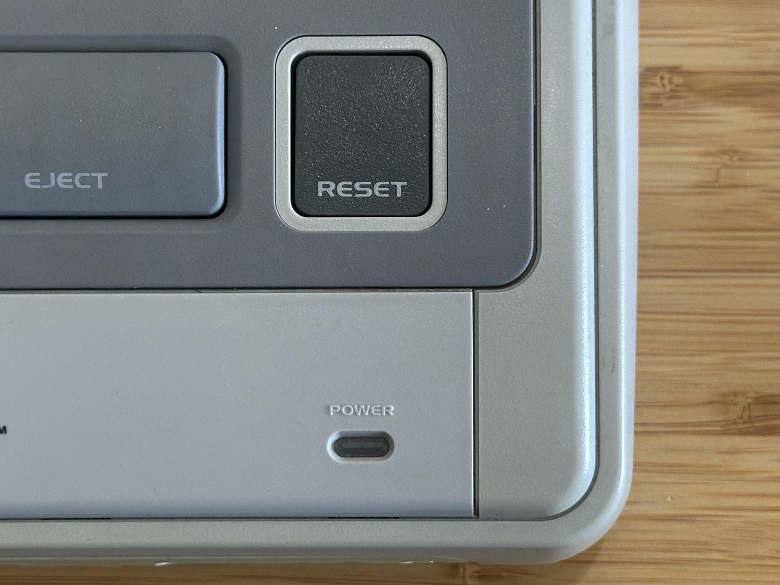
I’d opened the SNES because it wouldn’t power on and accidentally discovered that somebody had already given it one of the upgrades I might otherwise have wanted. The exact reset-button gestures still needed to be established once the console was running — more on that below.
The proposed fix
The Triad supply itself is a good-quality, appropriately rated unit:
- 9V DC
- 1.3A
- 5.5×2.1mm barrel connector
- centre-positive output
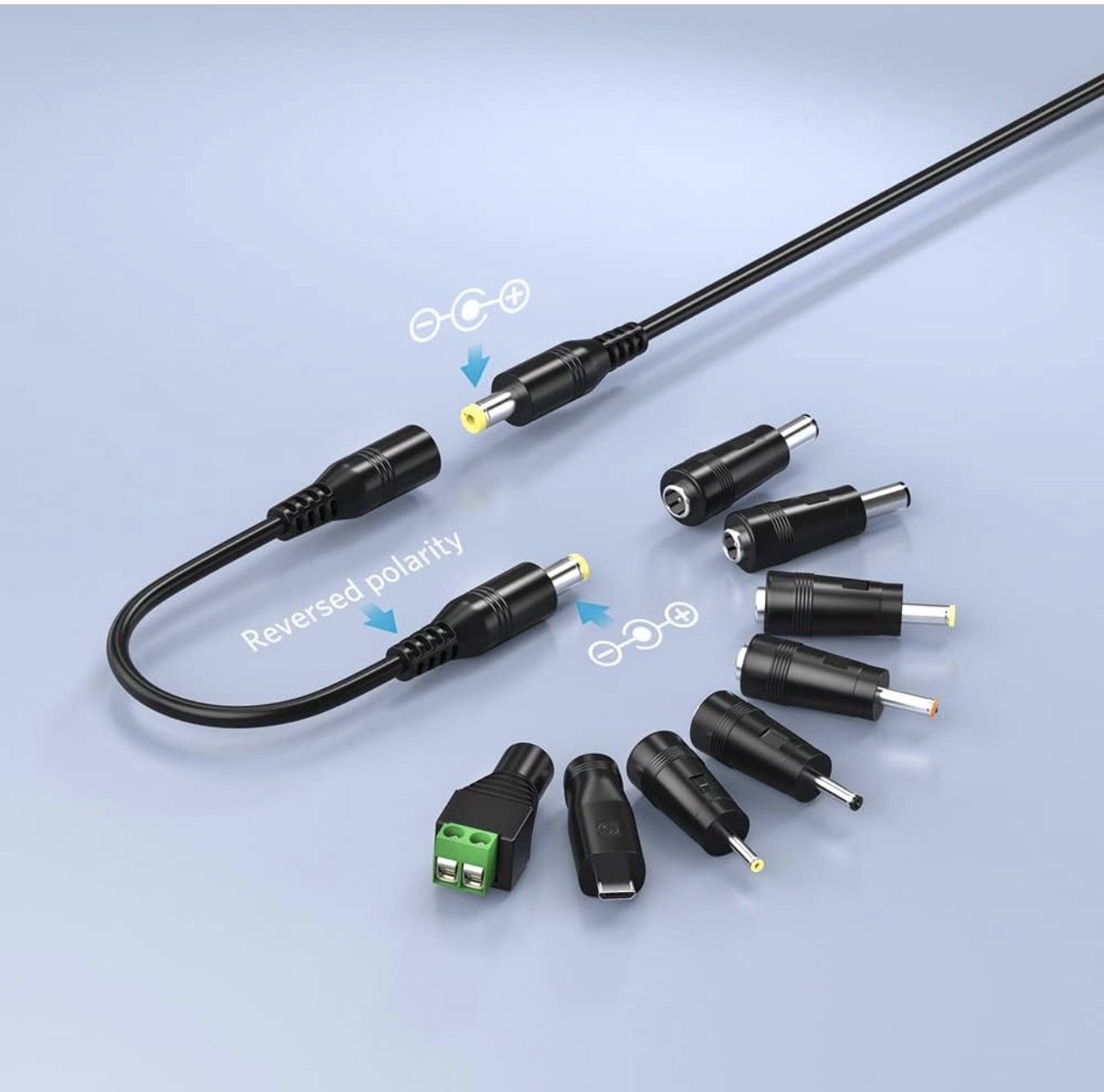
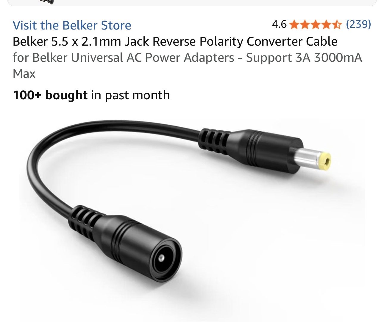
The voltage, current capacity and connector dimensions suit the console. Only the polarity is wrong. Rather than replacing the power supply, I bought a Belker 5.5×2.1mm polarity-reversing cable.
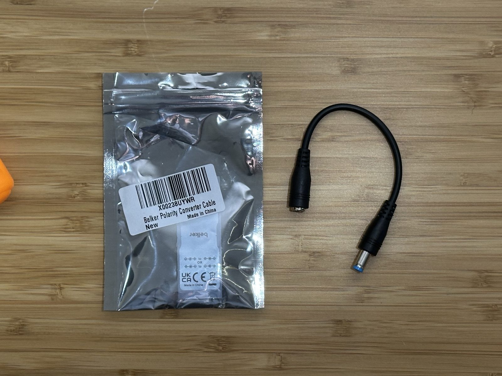
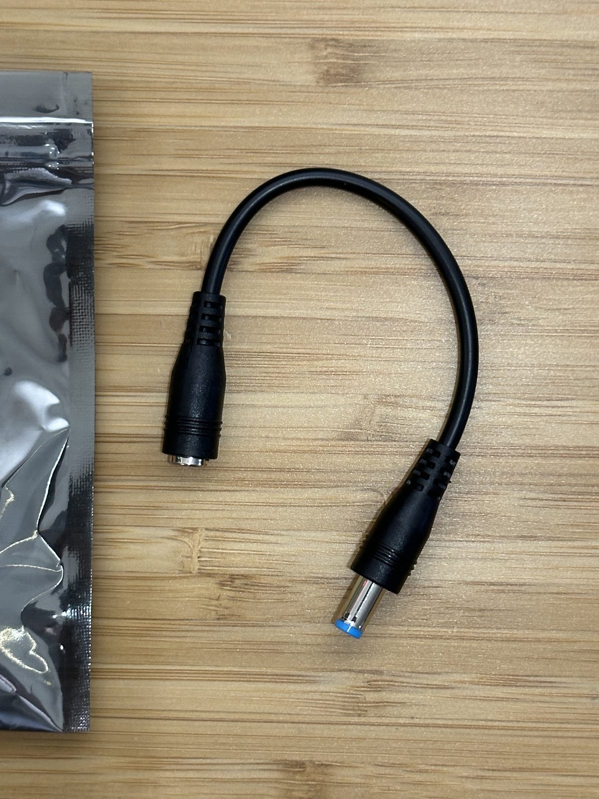
The final arrangement was therefore:
US mains → Triad WSU090-1300 → Belker polarity reverser → centre-negative 9V DC → SNES
Before the SNES became the first test load, I measured the final plug. With the black probe on the outer sleeve and the red probe on the centre contact, the multimeter showed approximately −9V. That confirmed the plug presented to the console was centre-negative.
Only then did I connect it to the SNES.
It works
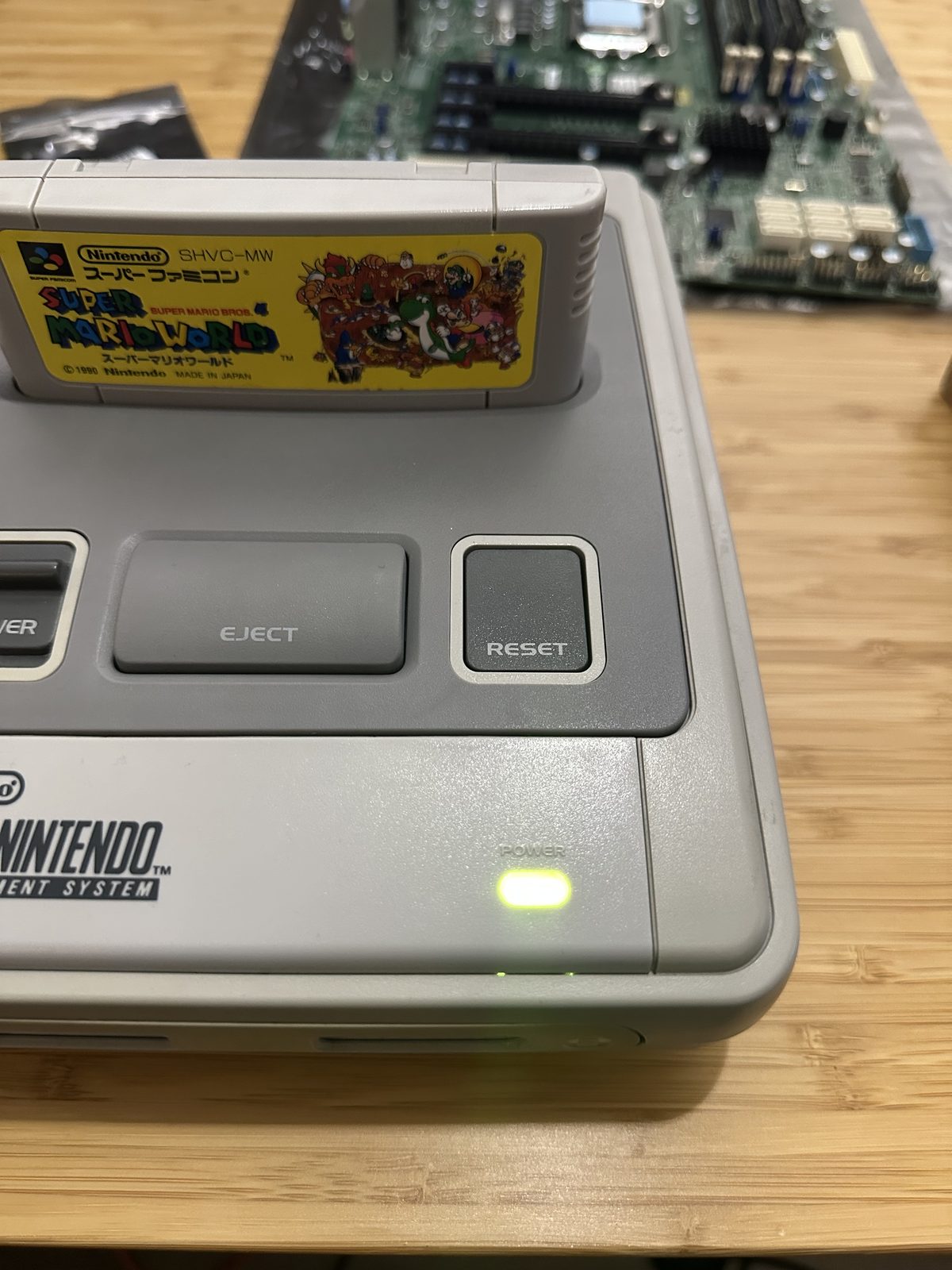
The power LED lit up — green, not red as I’d half-expected — and Super Mario World booted from the cartridge without any drama. No smoke, no dead board, no more strange voltages. Just a console doing exactly what it should have done from the start, once it was finally given power with the right polarity.
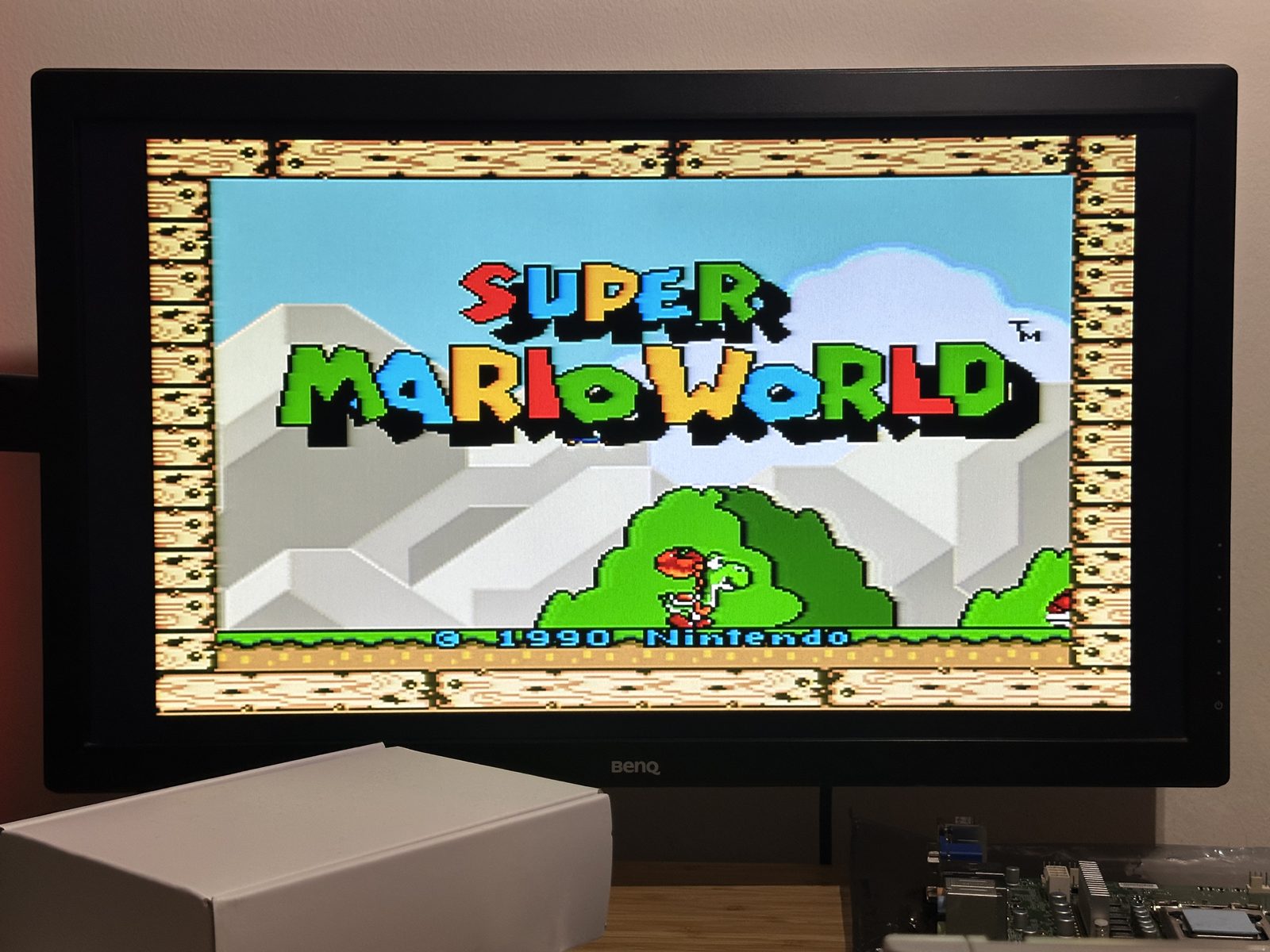
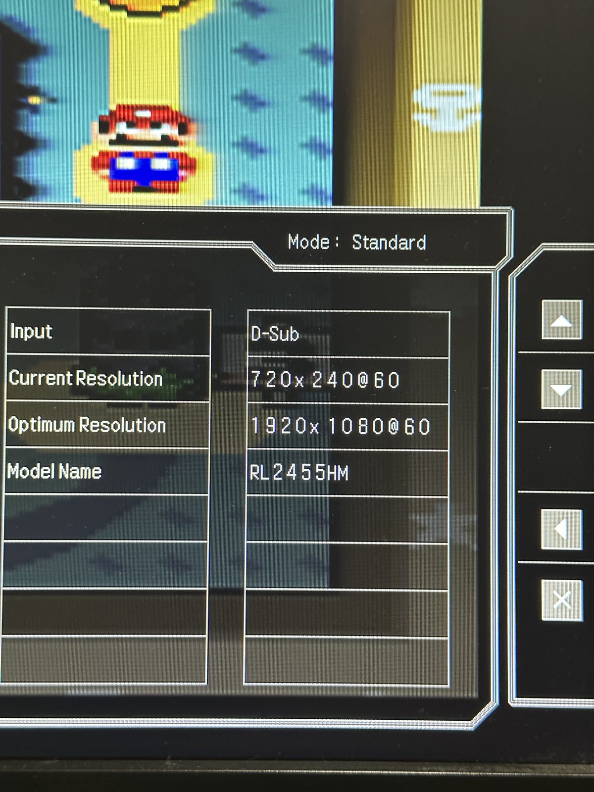
For anyone who wants the signal chain confirmed rather than taken on faith: the display’s own OSD shows a genuine 720×240 @ 60Hz input, scaled up to 1920×1080 — a real, clean 60Hz signal coming out of the console, not a fluke.
The conclusion turns out to be satisfyingly simple. The SNES was never broken. The new power supply was never broken either. I had simply bought the correct modern power adapter for a European-looking PAL SNES that — despite what it said on the lid — was actually built around a Japanese Super Famicom motherboard, and needed power the Super Famicom way.
The stealth mod, solved
One thread was still loose: what exactly did that hidden RESET-button wiring do? Holding the button down changes the power LED’s colour and switches the console between 50Hz and 60Hz — but I didn’t want to guess the exact behaviour from the wiring alone.
It turns out this is a well-documented, well-established combination in the SNES modding community, not a custom one-off: a SuperCIC (a PIC-based replacement for the console’s CIC lockout chip) paired with uIGR (“µIGR” / In-Game-Reset) firmware. Holding RESET cycles through three modes via the LED colour — 50Hz (green), 60Hz (red), and Auto-Region (yellow) — repurposing what would normally just be a lockout-chip status LED into the entire user interface for the mod. No external switch, no drilled hole, because the switch was never physical to begin with.
If you want to go deeper on the implementation, sd2snes.de’s SuperCIC and In Game Reset pages are about as close to canonical documentation as this mod has, and the uIGR firmware source is on GitHub.
So the final shape of this console: a PAL shell, a Super Famicom board, centre-negative power, and a completely invisible SuperCIC/uIGR region-free mod that I inherited without ever being told it was there. Not bad for a console I opened up expecting to just replace a blown fuse.
Related on this site
- Super Nintendo (SNES) — hardware reference page
